BOSS Riser Build, Part 1
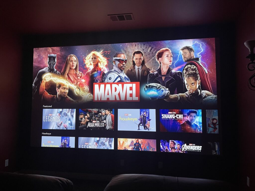
When I built my screen, I knew it was going to be big in the room, but I really liked the size and experience. The downside is that my second row of seats is on a 8″ riser and if you use a riser calculator with my seats and dimensions, the riser should be closer to 18″. So I started to research the best way to build my new riser, which of course led me to the AVSForum. As I researched risers, I came across the concept of a BOSS riser. You can read more here, but BOSS stands for Baffle Open Sub Shaker. Essentially, a BOSS riser connects to the sub out on your AVR using an external amp to provide amazing tactile response. This is similar to the concept of a Buttkicker or other amplified seat-shaker that augments your home theater experience. The previously mentioned thread is a wealth of great information, but its 380 pages of reading. So, I thought I would document my experience, hopefully providing some of that information in a single place.
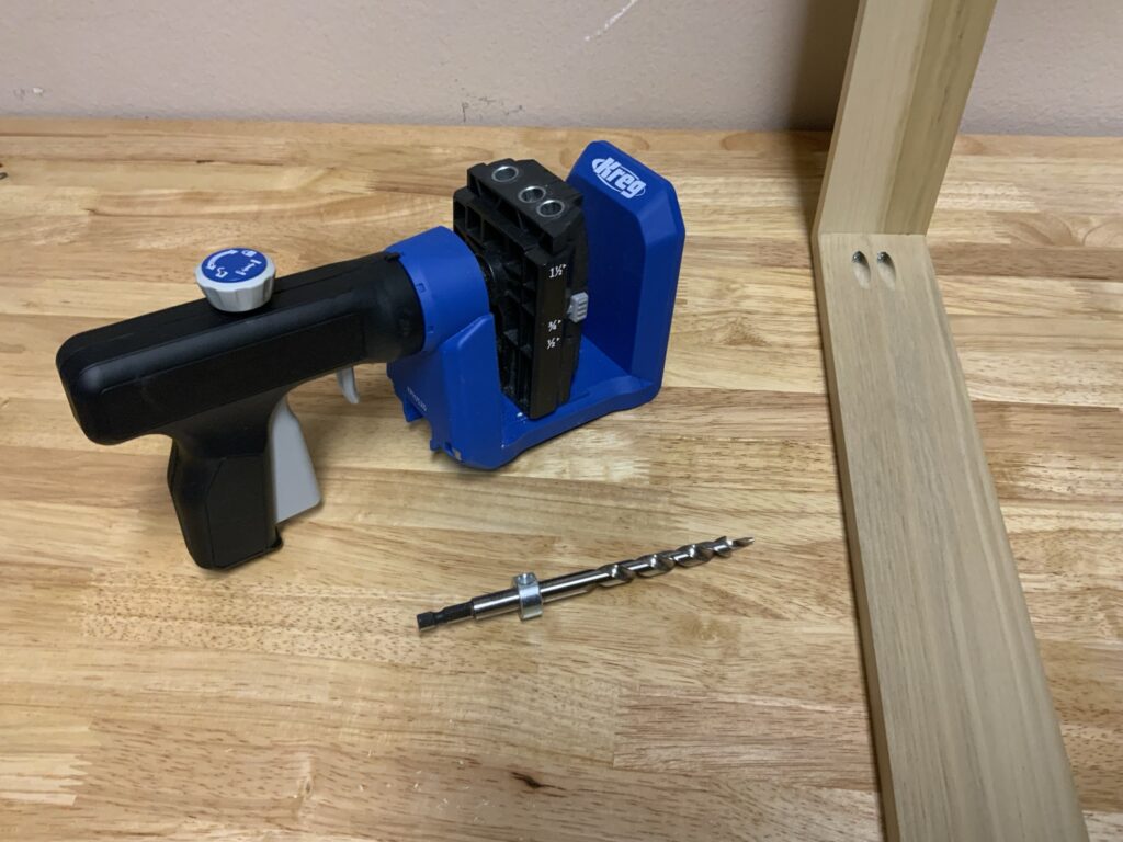
I’ll be constructing my riser in three basic stages: the riser build itself, finish work (trimming, painting, and carpeting), and finally shaking. This blog post will cover the riser built itself. This involves the actual base, the plywood top, and the of course, the subwoofer. I will also cover wiring up the subwoofers even though I won’t be adding the amp and such until later. Let’s start by taking a look at the tools I used. You might be able to get away with less tools, but this is what I used and would recommend.
BOSS Riser Tools Required:
- Miter Saw
- Circular Saw
- 8ft Cutting Guide
- Clamps (for the cutting guide)
- Router
- Hole Cutting Guide for Router
- Extra Straight Cutting Router Bit (for when mine broke)
- Impact Driver
- Power Screwdriver
- Drill
- Tape Measure
- Pencil
- Work Surface
- Soldering Iron
- Small Torch or Heat Gun
BOSS Riser Building Materials
Now that we have our tools lined up, we need something to build the riser out of. The size of the lumber you use will be dependent on your height, width, and depth requirements. I decided to use 2×8’s (7.5″) with a double plywood top (1.5″) resting on isolators (1″, which we’ talk about later) and carpet savers. This should give me about 10″ of additional height for the seats. Here’s the full list of materials I used:
- 2 @ 2×8 (10ft)
- 2 @ 2×8 (8ft)
- 3 @ ¾” 4×8 Plywood (I used sanded pine, 7-layer from Home Depot)
- 24 @ 2″ Platinum Silicone Hemisphere Bumper
- 24 @ Carpet Savers
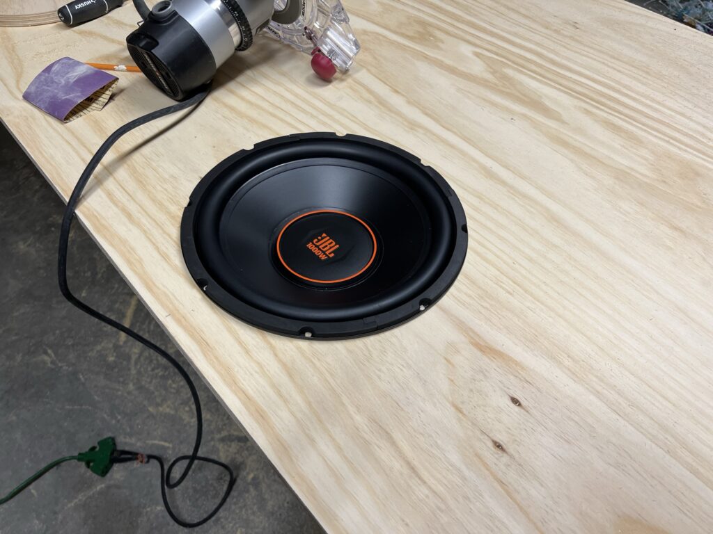
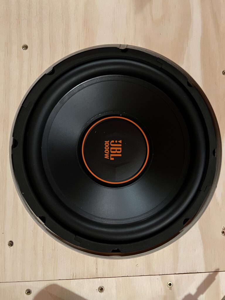
- 6 @ JBL GX1200
- 100ft @ Speaker Wire
- 6 + 6 @ Quick Splice Connectors
- Various Heat Shrink
- 1lb @ 3” Construction Screws
- 1lb @ 1 ¼” Construction Screws
- 1lb @ 1 ⅝” Drywall Screws
The Design
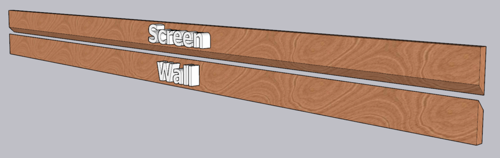
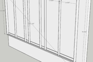
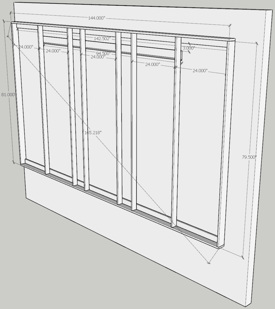
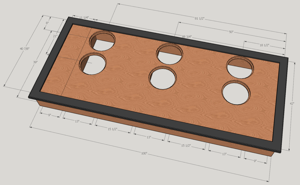
I’ve mentioned before how much I enjoy SketchUp, so of course I used it extensively for this process. Here’s the top view:
And here’s the bottom view:
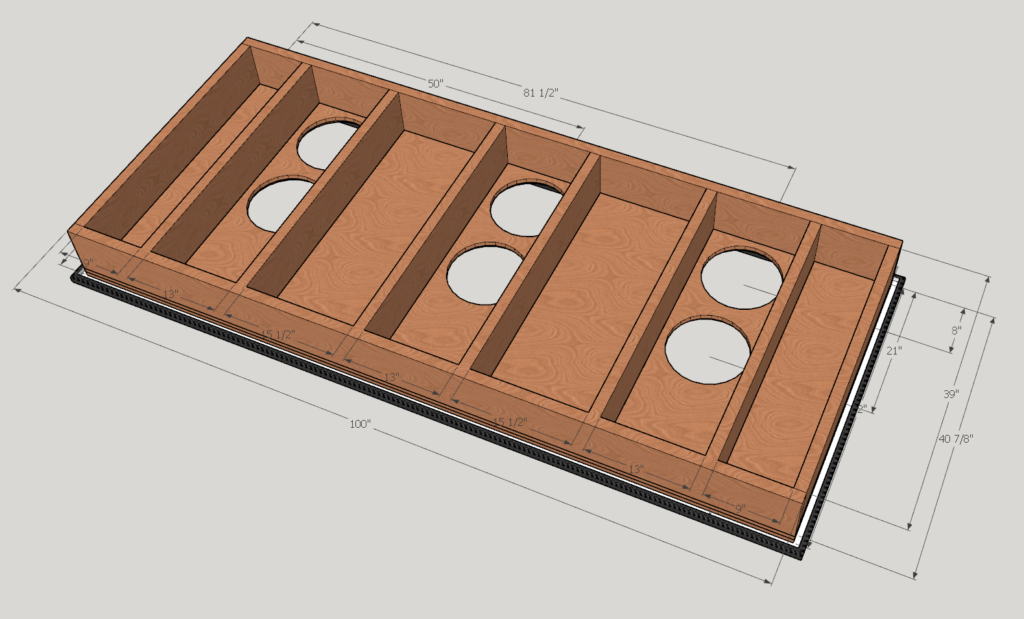
I tried to put my supporting structure right under the feet of my home theater seats. So I was less concerned about 16″ centers, and more concerned about it being supportive of the seats. I also had to piece in the plywood since 10ft plywood is obscenely expensive.
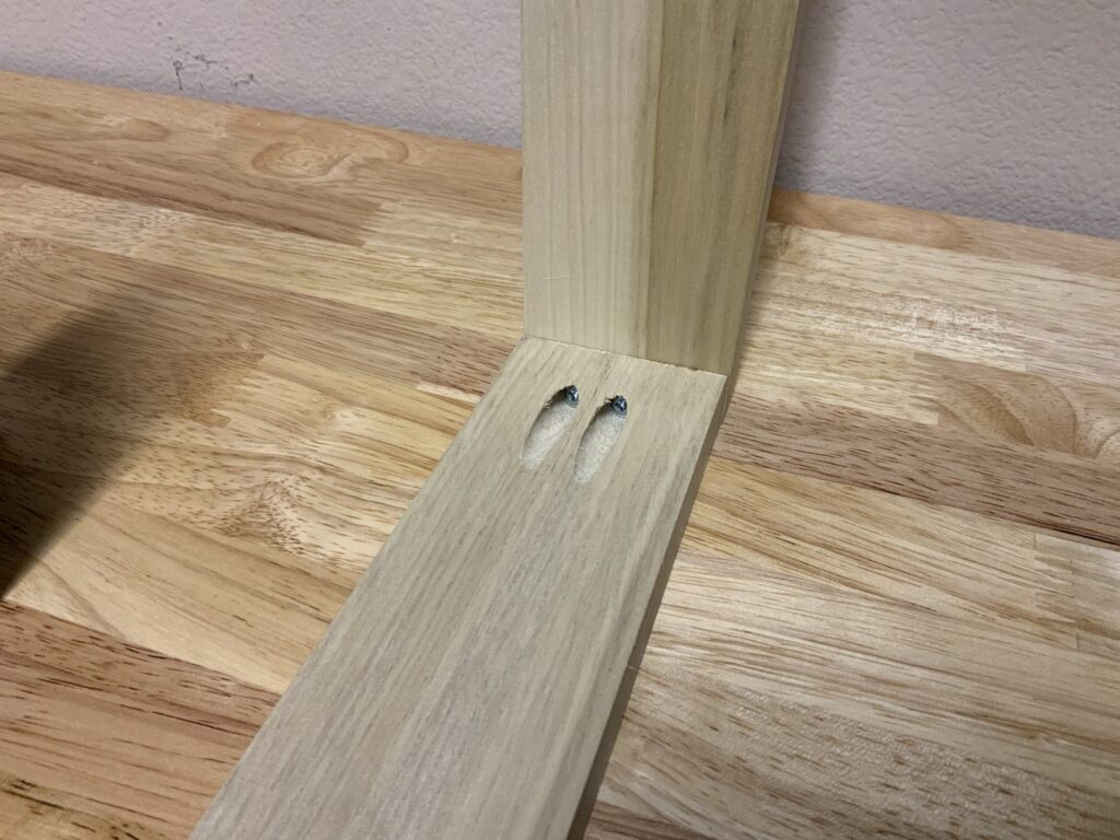
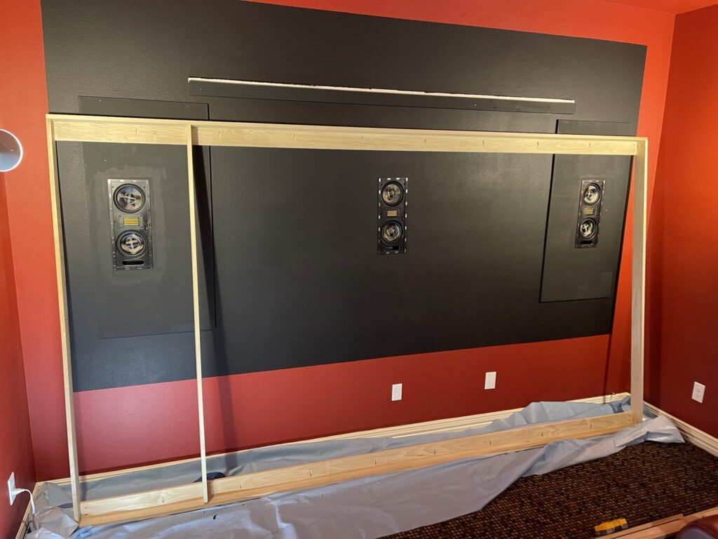
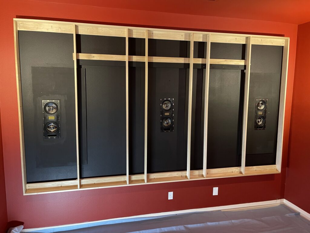
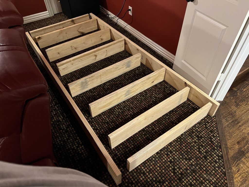
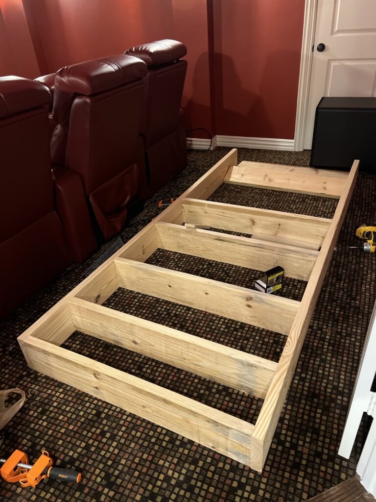
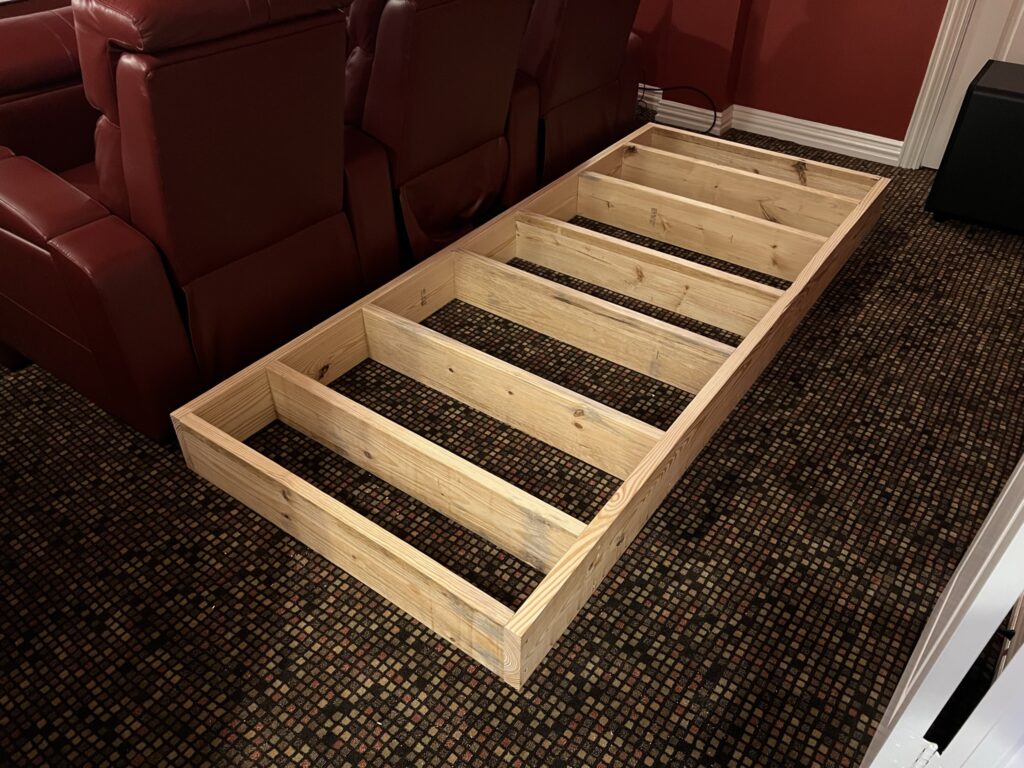
Building The Supporting Structure
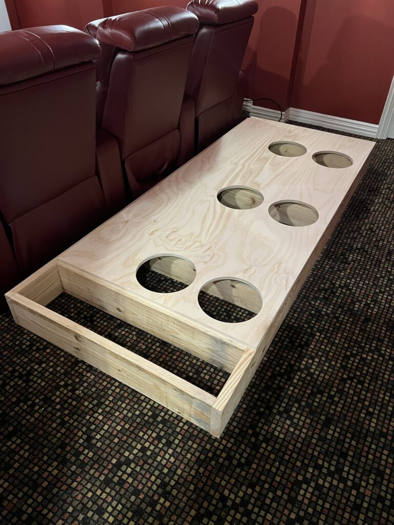
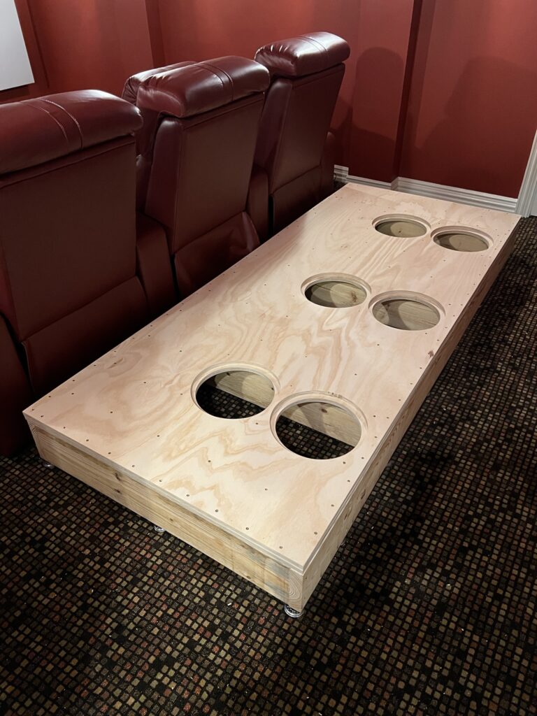
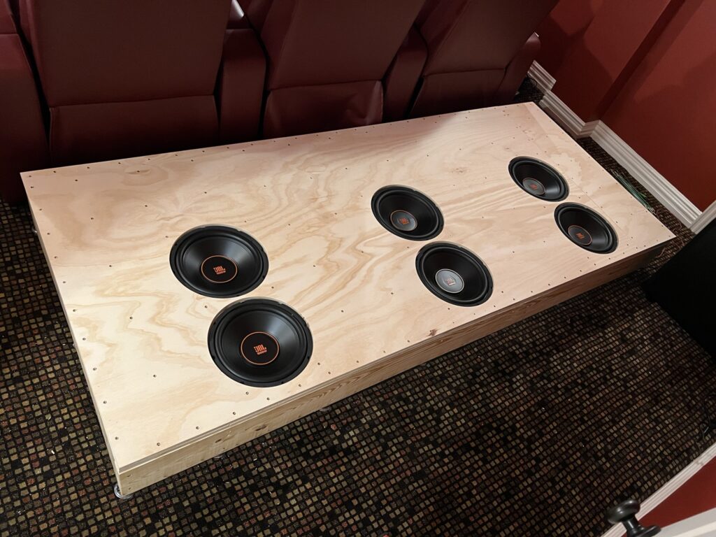
This was by far the easier part…it’s like framing a house. I cut two boards at 100″ and eight boards at 39″ giving me an overall platform size of 100″ x 42″. This is a pretty big platform, hence the six drivers. I screwed this together with 3″ construction screws:
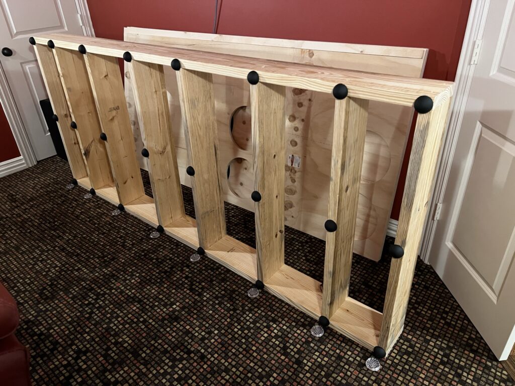
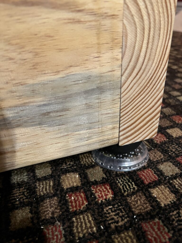
Isolators
Before we move on to the top, we need to talk about isolators. These are basically rubbery half-circles that isolate the riser from the room. This means that the power from the drivers stays contained in the riser and doesn’t transfer into the room. More shake! The guidance is every 24″, but I couldn’t quite make that work, so I ended up with three per support:
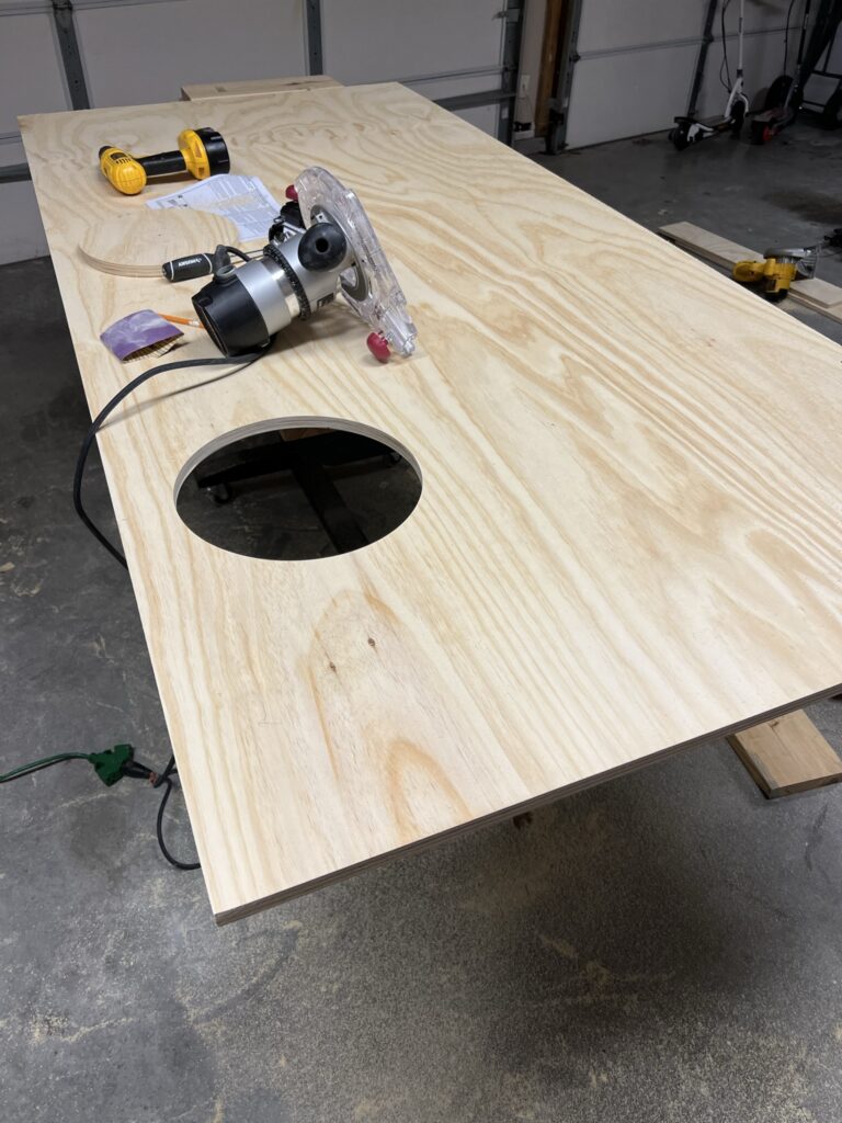
The Top
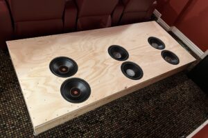
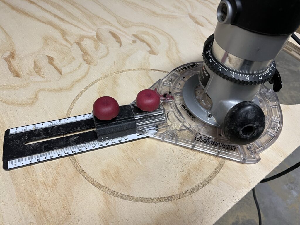
Now for the fun part…cutting giant holes. First I cut the plywood down using my circular saw and a straight cutting guide. Then I measured for the first hole and tried out my circle cutting guide for my router.
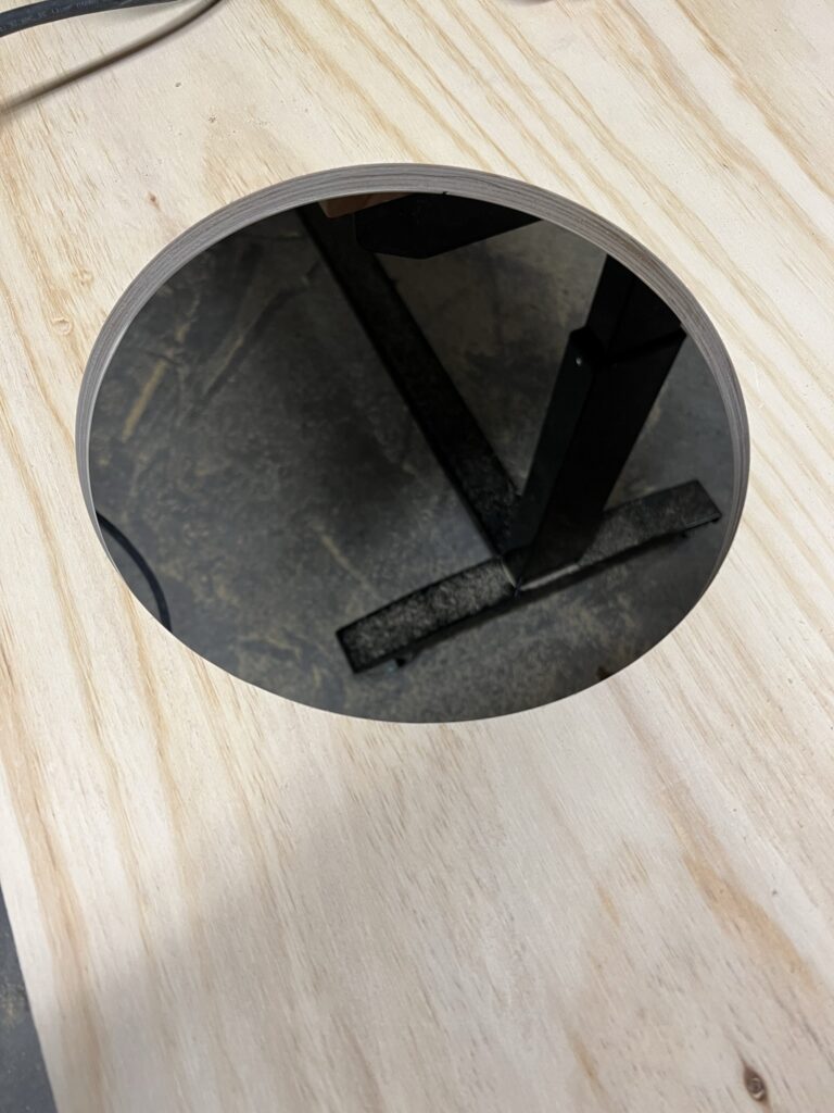
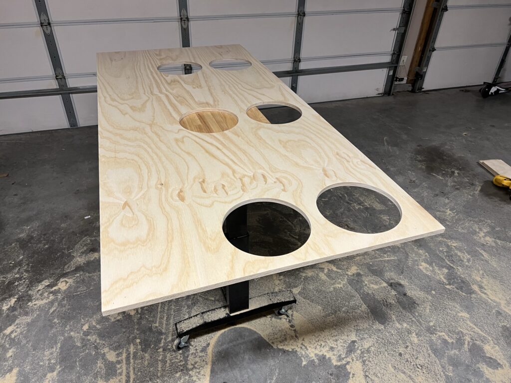
Now that the holes are cut we can dry fit it on the base:
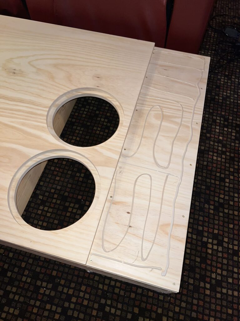
Next I measured and cut the extra ends to for both layers and dry fit those as well:
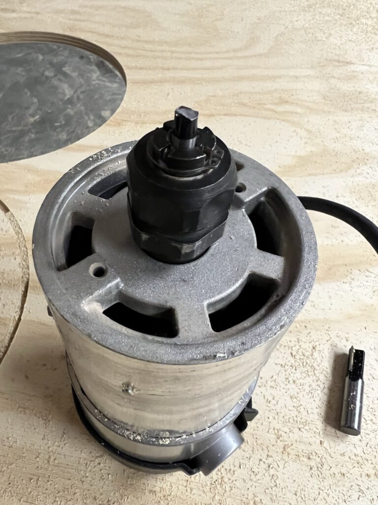
Now we can finish cutting the top, which has bigger holes (12.5″)…but before I could finish, I broke the bit. I think I let it heat up too much rather than waiting between holes. Luckily I had another bit.
Moving on…I finished the second layer of the top and then attached the first layer to the base with 1 1/4″ construction screws. Then I applied a layer of titebond wood glue and attached the second layer:
It should also be noted that the first layer was screwed on every 4 inches and the second layer was offset so that I didn’t hit the screws below. This made it 100% rock solid. I had my son (who is 6) jump up and down just to see it bounce a little on the isolators…pretty cool.
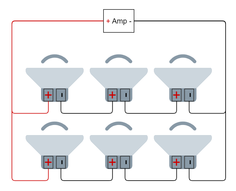
Wiring The Subs
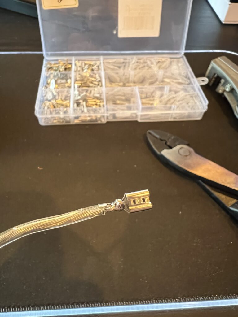
Once I finished the structure, it was time to wire up the speakers. With six speakers, the recommended configuration is one of series/parallel. Basically two sets of three speakers in series, and then those two sets in parallel. The math leads us to a 6 ohm load which will eventually be attached to an NX3000D in bridged mode. I soldered the negatives together on the last two speakers with connectors:
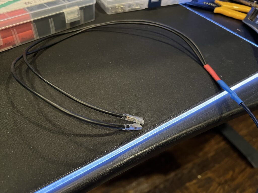
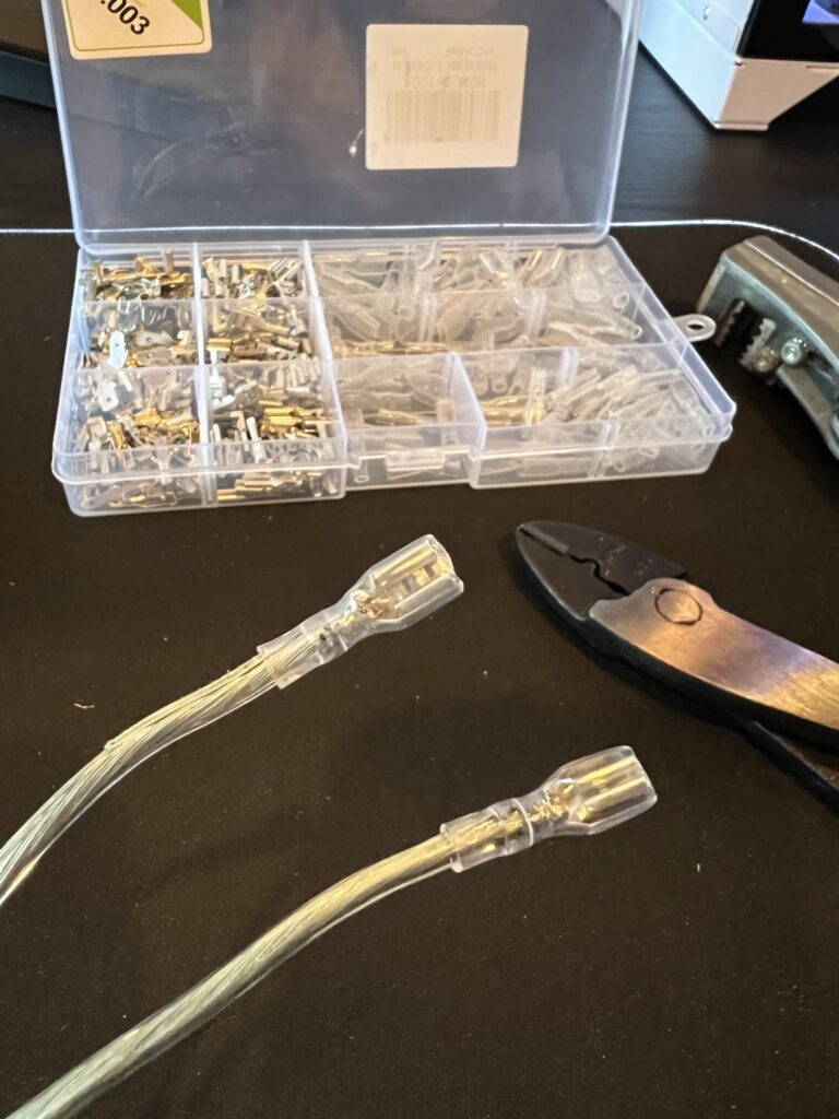
I did the same thing with a red wire for the positives of the first two speakers. Then I connected each speaker together with the negative of the first to the positive of the second and the negative of the second to the positive of the third. I soldered the connectors to the wires:
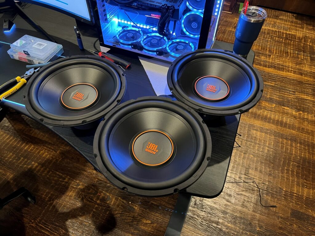
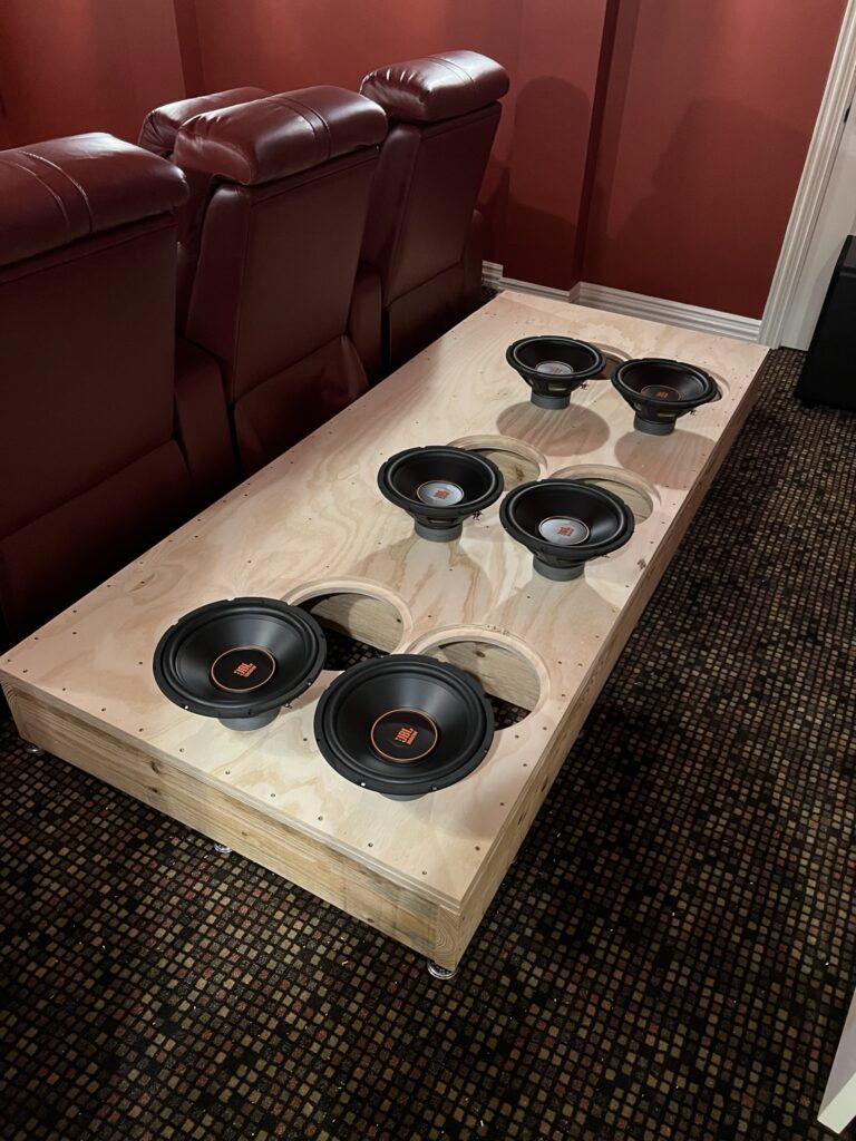
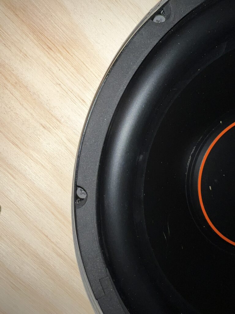
BOSS Riser Driver Installation
As this is a BOSS riser, I need lots of subs! Here are a few ready for installation:
Next up I set them on top to attach my connectors and run the wires. I made them a little shorter than intended so I had to wire and install each one rather than wiring them up and installing them all at once.
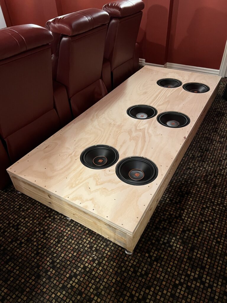
Conclusion
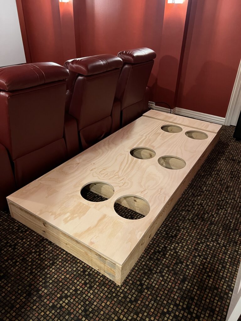
All in, this portion of the project took me roughly three nights of work. Two longer nights and a third night to finish it off during the week. Next up, we’ll add the Oak trim and get it all painted and carpeted! In the meantime, here is how it looks with my chairs finally high enough:
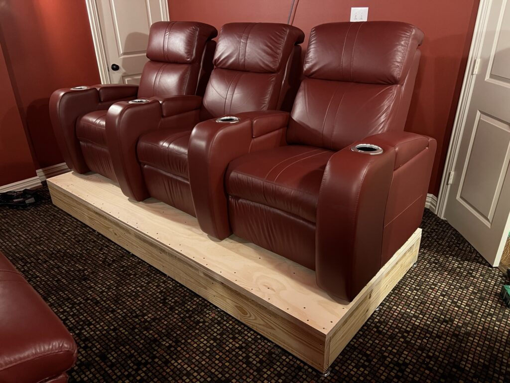
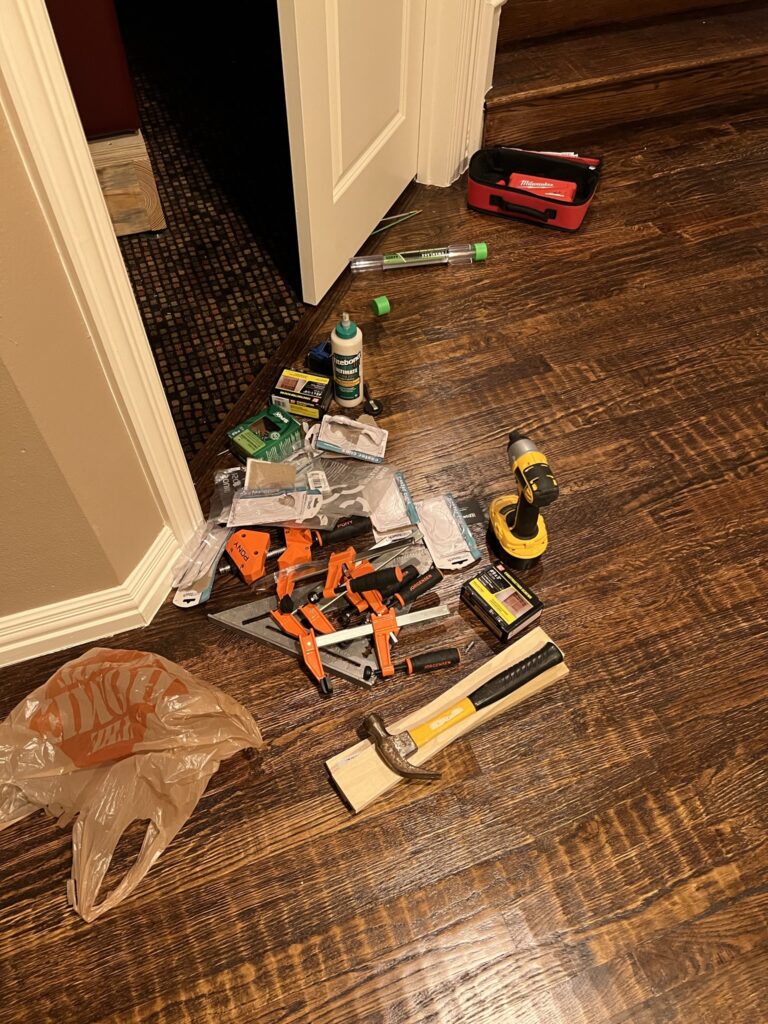
And here is the aftermath: